Sensor System Signal Acquisition, Event Detection and Configuration
- Arturo Arriaga

- Dec 20, 2021
- 2 min read
This project tests the sensor system signal acquisition, event detection and configuration of the STMicroelectronics SensorTile.

List of Equipment and Materials:
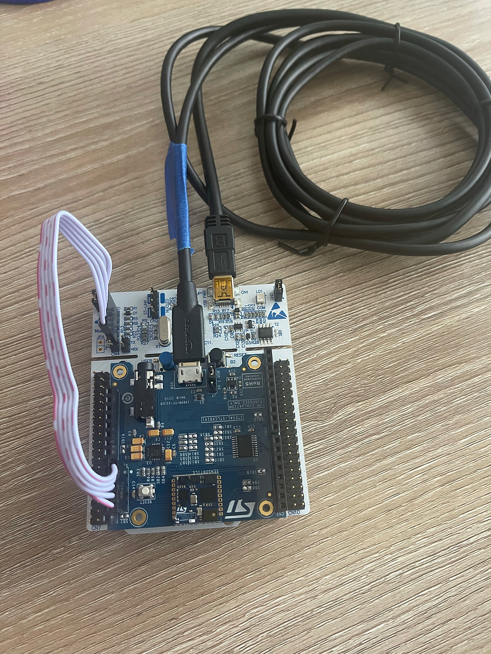
1x STMicroelectronics SensorTile kit.
1x STMicroelectronics Nucleo Board.
1x Personal Computer with two USB type-A inputs OR you must have a powered USB hub.
1x USB 2.0 A-Male to Micro-B Cable (micro USB cable).
1x USB 2.0 A-Male to Mini-B Cable (mini USB cable).
Network access to the Internet.
Modifying Sampling Rate: Output Data Rate:
First, we examine the Sensor Sampling Rate and Output Data Rate and then Modifying the USB Data Output Rate based on our desired rate.
Image shows 5 successive timestamps of the USB Data Output Rate. This is not the rate at which data is recorded by the sensor. This is the rate at which data is transmitted to the host computer over the serial USB data transport.
We only want the SensorTile to perform calculations once every time the data period (in milliseconds) has been reached. However, the processor may run the desired function several times before 1ms has elapsed, so this value must be adjusted.

Creating New Data, New Messages, and Event Detection:
These changes add information regarding computing vector magnitude acceleration from signals obtained from the accelerometer. The SensorTile accelerometer measures acceleration on each of three orthogonal axes, X, Y, and Z with acceleration values of ax, ay, and az, respectively.

We are going to add some information to the end of the Accelerometer output to inform the user of the magnitude of the acceleration vector. The new method will add a message to indicate that the acceleration vector magnitude has exceeded a certain threshold value.

Modifying Data Acquisition Parameters:
Here methods are adjusted to the sensor measurement range. Specifically, the SensorTile microaccelerometer Full-Scale measurement range (FS) is adjusted.
If we wish to see the magnitude exceed a value of 3.5g, we would need to adjust the parameters of the sensor such that it can record values greater than 2000 for each axis.
Gyroscope Modification:
The gyroscope handler function is modified such that it now computes the vector magnitude computation and transmits this computed value over the serial USB connection.

We then modify the system such that it now computes the vector magnitude computation and transmits this computed value over the serial USB connection once the angular velocity has surpassed a threshold value.


Comments